
Structures:
Stargazer 1-1.2
The ultimate goal of our initial Stargazer designs was to build a foundation of knowledge on how to design a multistage rocket. In line with our program's ultimate goal of reaching the Karman Line, the use of a high power multistage rocket would be inevitable. To lay the foundation for this future goal, a sub-scale, low power model would be developed, resulting in the stargazer 1 rocket. This rocket would follow common principles seen in most multistage rockets of this size, utilizing an intestate avionics bay and coupler.
Stargazer 1, would introduce us to the dynamic complexities seen within multistage rockets. Even among the low-power design of stargazer 1, we were required to delve into our restores , to successfully design our rocket. Given the short timeframe and budget, our design remained low-cost and conservative. We attempted to make a vehicle that could both be easily manufactured for a low scale attempt, all while having a design that could translate to a higher power vehicle. Ultimately, we were able to select the guiding principles we had to keep in mind throughout the design process. These, however, would grow more complex with the design of our high powered, stargazer 2 rocket.
Stargazer 1.1-1.2
As a result of the failed launches of stargazer 1 and 1.1, design modifications were made as we grew our knowledge base. Largely, our original dynamic understanding was sound, however with the rebuild of stargazer 1.1, we made a modification to the sustainers fins, allowing for a higher base stability design.

The failure of stargazer 1.1, demanded a full reconstruction of the rocket. However, due to a clear understanding of the means of failure on the rocket, no major design modifications were made. Changes, however, we’re made within other teams, to ensure easy assembly and integration.
Stargazer 2
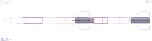
The Stargazer 2 rocket poised to be a monumental leap in the development within the Stargazer and Spaceshot program. For context, our program had never reached the heights or speeds expected by this new rocket, mandating a conservative approach to our design. In conjunction with this, our budget demanded a minimum viable product, further complicating our design process. As was done before with the Stargazer 1-1.2 designs, heavy reliance on outside resources were used, as our team was unfamiliar with the new challenges this rocket would deliver. Overall, however, our design remained relatively the same, using a constant diameter and a coupler interstage. This choice was made, as opposed to more advanced designs, due to its simplicity, and our familiarity with it on Stargazer 1-1.2.

Once a general design had been formed, we had to ensure the rocket was dynamically stable. Typical single stage rockets have standard principles for design regarding stability. These principals, however, would not always translate with our design. Given concerns such as pitch roll coupling, our design required the input from those who had flown this high and fast before, with help largely coming from online papers, our mentor John Willams, and Kip Daugirdas. Ultimately, once we had been able to determine the stability and overall design requirements of our dynamic design, we dove into designing the fins. Through countless iterations, we were ultimately able to produce a sufficient stability margin and altitude, with a design that could be easily manufactured.
As the semester progressed, we continued to solidify what our final design would look like. In continuation with our desire to remain conservative, we incorporated a number of design choices that would either hedge against potential mistakes, or protect us against unexpected conditions. Additions such as increased room for recovery and raising our min-d motor mount placement, all served to negate potential concerns, allowing us to focus on the fabrication and avionics integration into the rocket. Presently, simulations are ongoing into reducing drag, approximating coast time, and airframe buckling.
Stargazer 1 Manufacturing:
The goal of Stargazer 1 was to be a test rocket to iron out the issues of multi-staged rockets before moving into a full-scale, high-altitude rocket. From a manufacturing point of view, Stargazer 1 was a step back in composites. This was because the rocket’s airframe and aerodynamic surfaces were made of a combination of blue tube, cardboard, wood, and ABS. Composites were not necessary due to the lower expected loads on this subscale rocket as well as a need for a reduction in costs with a rocket that would go through many iterations. This is not to say there were no manufacturing challenges however. The Fabrication team had to assemble a two-stage rocket for the first time and the areas that proved to be difficult mainly centered around integration with other teams to ensure the rocket followed the concept of operations correctly.

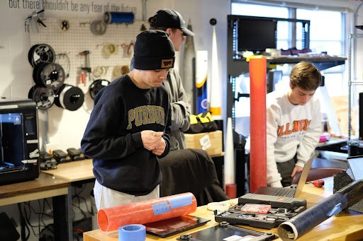
Stargazer 1 manufacturing session

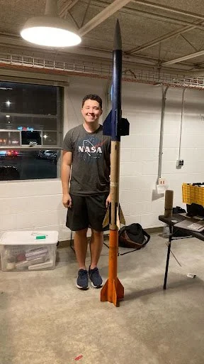
Stargazer 1 in final form
Stargazer 1 helped teach the Fabrication a lot in regards to how to properly assemble a multi-stage rocket as it is inherently more complex than a single-stage rocket even without the composites. And now with the success of Stargazer 1 in November of 2023, the Spaceshot project could move away from the subscale of Stargazer 1 and on to the full-scale high-altitude rocket of Stargazer 2 that would bring back all the composite work accomplished in the Intrepid era.
Stargazer 2 Manufacturing:
Preparation work for Stargazer 2 manufacturing
Avionics
Stargazer 1.0-1.2

Stargazer 1 integration session
Since Stargazer 1 had to be rebuilt twice, slight changes were made to the iterations such as a change in how the sustainer’s igniter was wired down the rocket or changes in motor selection. These were made in response to the failures seen in the first two launches with the changes ultimately resulting in the third attempt of Stagazer 1 working flawlessly.

Stargazer 1’s successful sustainer separation from the booster (bottom of the photo)
This year, the Fabrication team will combine the composites knowledge from Intrepid with the staging knowledge from Stargazer to create a 15 foot long rocket capable of shattering the UIUC altitude record and sending the Illinois Space Society to new heights. The material composition and manufacturing procedures for Stargazer 2 will be as follows:
Commercially procured fiberglass nose cone and airframe
Base fin plates are G10 fiberglass that will be cut and beveled to size
Fins are attached to the airframe using twill weave carbon fiber impregnated with high temperature epoxy resin
Fin layups will be vacuum bagged and autoclave post cured to achieve maximum material properties
Sustainer fin leading edges will be coated with an extremely high temperature epoxy
As Stargazer 1 was built to be a test rocket for future staging attempts, we had no need for an SRAD avionics system. As a result, for all three iterations, we used COTS altimeters in each stage with no additional avionics. E-matches and motor igniters were connected to the altimeters using Phoenix connectors mounted on the bulkhead the same way as for TARS.
Stargazer 1.0
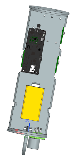
Stargazer 1.0 was designed and built in the span of roughly a month, and so the design was simple: each stage’s altimeters and batteries would be mounted on either side of a 3D-printed sled that sat on two threaded rods running through the length of their respective sections. The sled was secured in place by nuts on the exterior and interior of the bulkheads.
In the booster, we used a MiniTimer to fire the stage separation charge and a StratoLogger CF to fire the recovery charge. In the sustainer, we used an EasyMega for motor ignition and recovery, and a TeleMetrum as a redundant recovery altimeter and GPS tracker.

All separation events were controlled by black powder charges, and motor ignition was controlled using a standard motor igniter. However, because of high winds, the sustainer was tilted far past the tilt lockout set on the EasyMega, so the altimeter did not attempt to fire the motor.
Stargazer 1.1
Stargazer 1.1 used a similar avionics setup to Stargazer 1.0, with the addition of a downward-facing camera protruding from the side of the sustainer and a TeleMetrum in the booster for tracking. The TeleMetrum in the sustainer was also removed from flight event control and reduced to function as a GPS tracker. The camera was powered using two additional batteries inside the avionics bay and mounted under a 3D-printed cover that screwed into the revised avionics sled.

As in Stargazer 1.0, motor ignition was again controlled by a standard igniter, while all separation events were triggered using black powder charges. This time, even though the EasyMega attempted to fire the motor, the sustainer motor did not ignite, and the parachutes did not deploy.
On further inspection, we determined that the crash was the result of a complete power loss after the EasyMega attempted to fire the igniter, which required much more current to light than our batteries were capable of firing. This shorted out the altimeter’s power, causing it to cycle off and on again, which prevented the parachute deployment charge from being fired. Tragically, this failure cost us both the EasyMega and the TeleMetrum mounted in the booster.
Stargazer 1.2
Stargazer 1.2 used a setup corresponding to the wiring diagram below, using a TeleMega and a newly acquired Blue Raven altimeter for fully redundant motor ignition and parachute deployment in the sustainer and ditching the dedicated black powder stage separation for a “hot staging” where the sustainer motor’s ignition forced the booster to separate from the rocket. The booster was also wired redundantly, with two StratoLogger CF altimeters both firing the parachute deployment charge at roughly the same time.
To ensure that the motor would ignite this time, Structures assembled the motor with Pyrodex pellets that would fire the motor when ignited with an e-match. Thus, the power issues that we encountered in Stargazer 1.1’s flight were removed.

Recovery
Stargazer 1.0-1.2
The Stargazer series introduces new challenges and potential for the recovery team as the rocket requires three separations and two parachutes. Given the lower altitude and smaller rocket, the team worked to minimize the volume of the system by choosing a black powder based, single-deploy system.
Black powder ejection:

Parachutes:
For these proof of concept rockets, the team utilized black powder ejection. This works by burning the black powder at a designated altitude to create gas via the combustion reaction that pressurizes and separates the rocket. This occurs between stages first, then for lower stage parachute deployment, then upper stage deployment.


A single parachute resides in each stage. However, a reefing system similar to Intrepid III is utilized for the upper stage in order to minimize drift distance and help refine reefing mechanisms for future launches.
Coming up: Stargazer II
Stargazer II combines the most challenging aspects of Stargazer I and Intrepid III: high altitude launches and staging. To achieve the goals of a 100,000 foot attempt, recovery will use black powder separation in the lower stage and CO2 ejection in the upper stage with a drogue and main parachute in each stage.
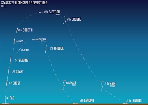
Separation:
The team will use black powder separation for interstage separation and booster parachute release. To ensure the successful burn of black powder at high altitudes with lower air density, the team plans to test combustion in a vacuum chamber to ensure the black powder is packed in an air tight manner. The Eagle CO2 system will be used in the upper stage in the same manner as Intrepid III.
Parachutes:
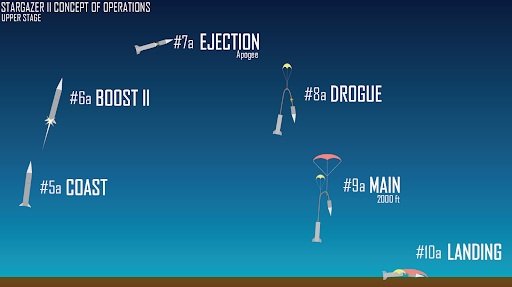
The booster and sustainer stages use the same dual parachute system. At apogee, the drogue parachute deploys. The main parachute is wrapped in a kevlar chute protector and is zip tied to the shock cord with a Piranha Line Cutter. At 2,000 feet, the line cutter cuts the zip tie and the main parachute deploys. This allowed both stages to be recovered safely while minimizing drift.